
Page 160 - Fiber Bragg Gratings
P. 160
4.2 Coupled-mode theory 137
similar set of circles intersects the free space shaded inner circle to define
the cutoff of all cladding modes. Beyond this point and into the inner
shaded circle is the radiation field region. If the cladding were extended
to infinity, the middle circle would become the locus of all cladding space
modes (continuum). In the present situation, the inner circle remains the
locus of the free space modes, which are the cladding modes beyond cutoff.
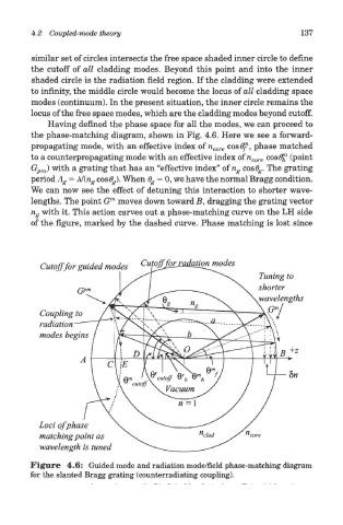
Having defined the phase space for all the modes, we can proceed to
the phase-matching diagram, shown in Fig. 4.6. Here we see a forward-
1
propagating mode, with an effective index of n core cosfff , phase matched
to a counterpropagating mode with an effective index of n core cos (9^ (point
G pm) with a grating that has an "effective index" of n g cos0 g. The grating
period A g = A/(n g cos6 g). When 6 g — 0, we have the normal Bragg condition.
We can now see the effect of detuning this interaction to shorter wave-
m
lengths. The point G moves down toward B, dragging the grating vector
n g with it. This action carves out a phase-matching curve on the LH side
of the figure, marked by the dashed curve. Phase matching is lost since
Figure 4.6: Guided mode and radiation mode/field phase-matching diagram
for the slanted Bragg grating (counterradiating coupling).