
Page 233 - Fiber Bragg Gratings
P. 233
210 Chapters Apodization of Fiber Gratings
mation is possible with a few cycles. In order to invert the phase between
the sections, additional UV exposure is given to induce a A/2 phase shift.
The MPF scheme caters for both the changes in the amplitude of the
refractive index modulation and the phase change. For the former, overlaid
subgratings with the appropriate phase step between each printing reduce
the fundamental component of the amplitude of the refractive index modu-
lation. By the same technique, a phase change of TT can also be introduced
by shifting the fiber by the appropriate distance prior to the printing of
the next subgrating. This method allows a very high degree of flexibility
in the fabrication of gratings [17].
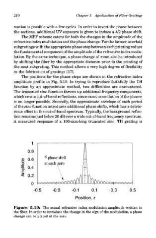
The positions for the phase steps are shown in the refractive index
amplitude profile in Fig. 5.10. In trying to reproduce faithfully the TH
function by an approximate method, two difficulties are encountered.
The truncated sine function throws up additional frequency components,
which create out-of-band reflections, since exact cancellation of the phases
is no longer possible. Secondly, the approximate envelope of each period
of the sine function introduces additional phase shifts, which has a delete-
rious effect in the out-of-band spectrum. Typically, the background reflec-
tion remains just below 20 dB over a wide out-of-band frequency spectrum.
A measured response of a 100-mm-long truncated sine, TH grating is
Figure 5.10: The actual refractive index modulation amplitude written in
the fiber. In order to introduce the change in the sign of the modulation, a phase
change can be placed at the zero.