
Page 238 - Fiber Bragg Gratings
P. 238
5.2 Basic principles and methodology 215
In Eq. (5.2.13), the denominator is approximately the Bragg wave-
length X e "phase matched" to the period of the envelope, so that the frac-
tional change in the fundamental Bragg wavelength is the same as the
ratio of the two wavelengths.
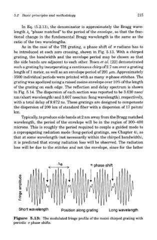
As in the case of the TH grating, a phase shift of TT radians has to
be introduced at each zero crossing, shown in Fig. 5.13. With a chirped
grating, the bandwidth and the envelope period may be chosen so that
the side bands are adjacent to each other. Ibsen et al. [22] demonstrated
such a grating by incorporating a continuous chirp of 2.7 nm over a grating
length of 1 meter, as well as an envelope period of 291 /u,m. Approximately
3500 individual periods were printed with as many Tr-phase stitches. The
grating was apodized using a raised cosine envelope over 10% of the length
of the grating on each edge. The reflection and delay spectrum is shown
in Fig. 5.14. The dispersion of each section was reported to be 3.630 nsec/
nm (short wavelength) and 3.607 nsec/nm (long wavelength), respectively,
with a total delay of 9.672 ns. These gratings are designed to compensate
the dispersion of 200 km of standard fiber with a dispersion of 17 ps/nm/
km.
Typically, to produce side bands at 2 nm away from the Bragg matched
wavelength, the period of the envelope will be in the region of 300-400
microns. This is roughly the period required to couple a guided mode to
a copropagating radiation mode (long-period gratings, see Chapter 4), so
that at some wavelength (not necessarily within the chirped bandwidth),
it is predicted that strong radiation loss will be observed. The radiation
loss will be due to the stitches and not the envelope, since for the latter
Figure 5.13: The modulated fringe profile of the moire chirped grating with
periodic TT phase shifts.