
Page 234 - Fiber Bragg Gratings
P. 234
5.2 Basic principles and methodology 211
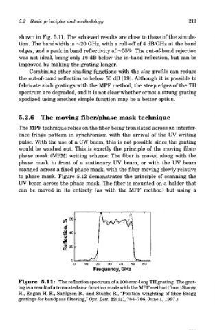
shown in Fig. 5.11. The achieved results are close to those of the simula-
tion. The bandwidth is -20 GHz, with a roll-off of 4 dB/GHz at the band
edges, and a peak in band reflectivity of —55%. The out-of-band rejection
was not ideal, being only 16 dB below the in-band reflection, but can be
improved by making the grating longer.
Combining other shading functions with the sine profile can reduce
the out-of-band reflection to below 50 dB [19]. Although it is possible to
fabricate such gratings with the MPF method, the steep edges of the TH
spectrum are degraded, and it is not clear whether or not a strong grating
apodized using another simple function may be a better option.
5.2.6 The moving fiber/phase mask technique
The MPF technique relies on the fiber being translated across an interfer-
ence fringe pattern in synchronism with the arrival of the UV writing
pulse. With the use of a CW beam, this is not possible since the grating
would be washed out. This is exactly the principle of the moving fiber/
phase mask (MPM) writing scheme: The fiber is moved along with the
phase mask in front of a stationary UV beam, or with the UV beam
scanned across a fixed phase mask, with the fiber moving slowly relative
to phase mask. Figure 5.12 demonstrates the principle of scanning the
UV beam across the phase mask. The fiber is mounted on a holder that
can be moved in its entirety (as with the MPF method) but using a
Figure 5.11: The reflection spectrum of a 100-mm-long TH grating. The grat-
ing is a result of a truncated sine function made with the MPF method (from: Stor0y
H., Engan H. E., Sahlgren B., and Stubbe R., "Position weighting of fiber Bragg
gratings for bandpass filtering," Opt. Lett. 22(11), 784-786, June 1,1997.)