
Page 235 - Fiber Bragg Gratings
P. 235
212 Chapters Apodization of Fiber Gratings
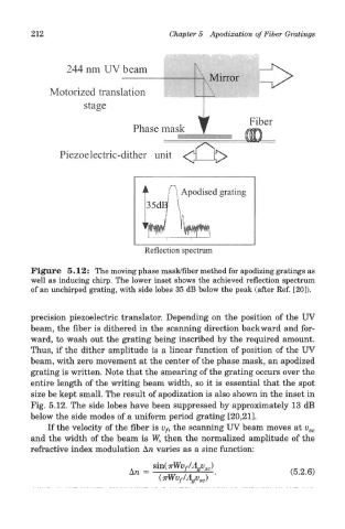
Figure 5.12: The moving phase mask/fiber method for apodizing gratings as
well as inducing chirp. The lower inset shows the achieved reflection spectrum
of an unchirped grating, with side lobes 35 dB below the peak (after Ref. [20]).
precision piezoelectric translator. Depending on the position of the UV
beam, the fiber is dithered in the scanning direction backward and for-
ward, to wash out the grating being inscribed by the required amount.
Thus, if the dither amplitude is a linear function of position of the UV
beam, with zero movement at the center of the phase mask, an apodized
grating is written. Note that the smearing of the grating occurs over the
entire length of the writing beam width, so it is essential that the spot
size be kept small. The result of apodization is also shown in the inset in
Fig. 5.12. The side lobes have been suppressed by approximately 13 dB
below the side modes of a uniform period grating [20,21].
If the velocity of the fiber is Vf, the scanning UV beam moves at v sc
and the width of the beam is W, then the normalized amplitude of the
refractive index modulation Arc varies as a sine function: