
Page 187 - Fiber Fracture
P. 187
172 J.G. Lavin
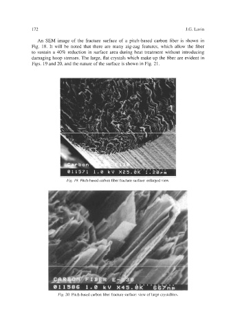
An SEM image of the fracture surface of a pitch-based carbon fiber is shown in
Fig. 18. It will be noted that there are many zig-zag features, which allow the fiber
to sustain a 40% reduction in surface area during heat treatment without introducing
damaging hoop stresses. The large, flat crystals which make up the fiber are evident in
Figs. 19 and 20, and the nature of the surface is shown in Fig. 21.
Fig. 19. Pitch-based carbon fiber fracture surface: enlarged view.
Fig. 20. Pitch-based carbon fiber fracture surface: view of large crystallites.