
Page 190 - Fiber Fracture
P. 190
FRACTURE OF CARBON FIBERS 175
(C) (4
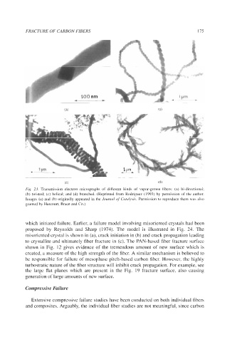
Fig. 23. Transmission electron micrographs of different kinds of vapor-grown fibers: (a) bi-directional;
(b) twisted; (c) helical; and (d) branched. (Reprinted from Rodriguez (1993) by permission of the author.
Images (a) and (b) originally appeared in the Journal of Catalysis. Permission to reproduce them was also
granted by Harcourt, Brace and Co.)
which initiated failure. Earlier, a failure model involving misoriented crystals had been
proposed by Reynolds and Sharp (1974). The model is illustrated in Fig. 24. The
misoriented crystal is shown in (a), crack initiation in (b) and crack propagation leading
to crystallite and ultimately fiber fracture in (c). The PAN-based fiber fracture surface
shown in Fig. 12 gives evidence of the tremendous amount of new surface which is
created, a measure of the high strength of the fiber. A similar mechanism is believed to
be responsible for failure of mesophase pitch-based carbon fiber. However, the highly
turbostratic nature of the fiber structure will inhibit crack propagation. For example, see
the large flat planes which are present in the Fig. 19 fracture surface, also causing
generation of large amounts of new surface.
Compressive Failure
Extensive compressive failure studies have been conducted on both individual fibers
and composites. Arguably, the individual fiber studies are not meaningful, since carbon