
Page 273 - Fiber Fracture
P. 273
256 K. Yoshida
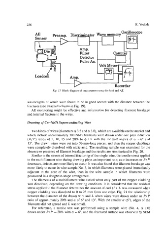
wavelengths of which were found to be in good accord with the distance between the
fractures (see attached schema in Fig. 19).
AE monitoring might be effective and informative for detecting filamcnt breakage
and internal fracture in the wires.
Drawing of Cu-NbTi Superconducting Wire
Two kinds of wires (diameters 4 3.2 and 4 3.0), which are available on the market and
which include approximately 300 NbTi filaments were drawn under one pass reduction
(RIP) ratios of 5, 10, 15 and 20% to Q 1.8 with the die half angles of (Y = 6" and
13". The drawn wires were cut into 50-mm-long pieces, and then the copper claddings
were completely dissolved with nitric acid. The resulting sample was examined for the
absence or presence of filament breakage and the results are summarized in Fig. 20.
Similar to the causes of internal fracturing of the single wire, the tensile stress applied
to the multifilament wire during drawing plays an important role; as a! increases or RIP
decreases, defects are more likely to occur. It was also found that filament breakage was
more likely to occur in wire sample No. 3, in which filaments were placed immediately
adjacent to the core of the wire, than in the wire sample in which filaments were
positioned in a doughnut-shape arrangement.
The filaments of a multifilament wire curled when only part of the copper cladding
was dissolved, depending on the drawing condition. It is considered that the residual
stress applied to the filament determines the amount of curl (L). L was measured when
copper cladding was dissolved to 0 to 25 mm from one edge. Fig. 21 the relationship
between the diameter of the drawn wire and L when wires were drawn under an RIP
ratio of approximately 20% and (Y of 6" and 13". With the smaller (Y (6"), edges of the
filaments did not spread and L was small.
For reference, a tensile test was performed using a sample wire (No. 4, 4 2.0)
drawn under RIP = 20% with (Y = 6", and the fractured surface was observed by SEM