
Page 271 - Fiber Fracture
P. 271
254 K. Yoshida
drawing stress was high and the wire could not tolerate the stress generated under this
condition, the inclusion could not pass through the die and the wire broke.
FILAMENT BREAKAGE DURING COMPOSITE WIREDRAWING
In the fabrication technology of various composite wires, internal fracture and
filament breakage of the wire are fatal to the wire quality. The detection of wire defects
is extremely difficult, since most of the defects exist inside the wire and cannot be
detected by surface observation. In this study, defects of copper-clad nickel wire and
composite wires such as Cu-NbTi superconducting wire are detected during the drawing
process through acoustic emission (AE) measurement, and also the applicability of these
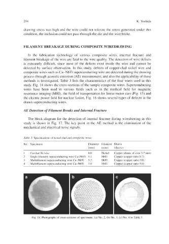
methods is investigated. Table 3 lists the characteristics of the four wires used in this
study. Fig. 14 shows the cross-sections of the sample composite wires. Superconducting
wires have been used in various fields such as in the medical field for magnetic
resonance imaging (MRI), the field of transportation for linear motor cars (Fig. 15) and
the electric power field for nuclear fusion. Fig. 16 shows several types of defects in the
drawn superconducting wires.
AE Detection of Filament Breaks and Internal Fracture
The block diagram for the detection of internal fracture during wiredrawing in this
study is shown in Fig. 17. The key point in the AE method is the elimination of the
mechanical and electrical noise signals.
Table 3. Specifications of tested clad and composite wires
~~ ~~
No. Specimens Diameter Filament Matrix
(mm) (core) (sleeve)
1 Cu-clad Ni wire 8.0 Nickel Copper (diam. of core 3.7 mm)
2 Single filament superconducting wire Cu-NbTi 5.1 NbTi Copper (copper ratio 0.7)
3 Multifilament superconducting wire Cu-NbTi 3.2 NbTi Copper (copper ratio 3.0)
4 Multifilament superconducting wire Cu-NbTi 3.0 NbTi Copper (copper ratio 5.0)
Fig. 14. Photographs of cross-sections of specimens: (a) No. 2, (b) No. 3, (c) No. 4 in Table 3