
Page 266 - Fiber Fracture
P. 266
FRACTURE OF SUPERFINE METALLIC WIRES 249
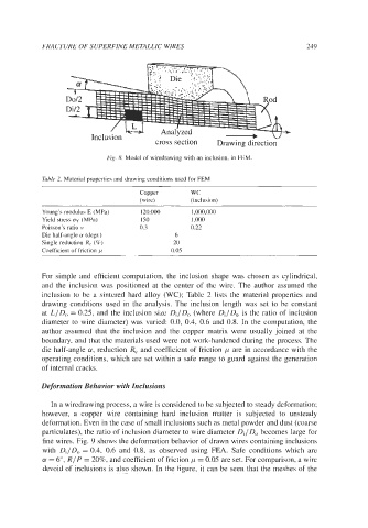
Fig. 8. Model of wiredrawing with an inclusion, in FEM.
Table 2. Material properties and drawing conditions used for FEM
Copper WC
(wire) (inclusion)
Young's modulus E (MPa) 120,000 1,000,000
Yield stress cry (MPa) 150 1,000
Poisson's ratio IJ 0.3 0.22
Die half-angle a (degr.) 6
Single reduction Re (%) 20
Coefficient of friction p 0.05
For simple and efficient computation, the inclusion shape was chosen as cylindrical,
and the inclusion was positioned at the center of the wire. The author assumed the
inclusion to be a sintered hard alloy (WC); Table 2 lists the material properties and
drawing conditions used in the analysis. The inclusion length was set to be constant
at LIDo = 0.25, and the inclusion size Di/D, (where DilD, is the ratio of inclusion
diameter to wire diameter) was varied: 0.0, 0.4, 0.6 and 0.8. In the computation, the
author assumed that the inclusion and the copper matrix were usually joined at the
boundary, and that the materials used were not work-hardened during the process. The
die half-angle a, reduction Re and coefficient of friction p are in accordance with the
operating conditions, which are set within a safe range to guard against the generation
of internal cracks.
Deformation Behavior with Inclusions
In a wiredrawing process, a wire is considered to be subjected to steady deformation;
however, a copper wire containing hard inclusion matter is subjected to unsteady
deformation. Even in the case of small inclusions such as metal powder and dust (coarse
particulates), the ratio of inclusion diameter to wire diameter DJD, becomes large for
fine wires. Fig. 9 shows the deformation behavior of drawn wires containing inclusions
with Di/D, = 0.4, 0.6 and 0.8, as observed using FEA. Safe conditions which are
a! = 6", R/ P = 20%, and coefficient of friction p = 0.05 are set. For comparison, a wire
devoid of inclusions is also shown. In the figure, it can be seen that the meshes of the