
Page 267 - Fiber Fracture
P. 267
250 K. Yoshida
.-
Inclusion
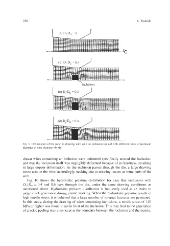
Fig. 9. Deformation of the mesh in drawing wire with no inclusion (a) and with different ratios of inclusion
diameter to wire diameter (b-d).
drawn wires containing an inclusion were deformed specifically around the inclusion,
and that the inclusion itself was negligibly deformed because of its hardness, resulting
in large copper deformation. As the inclusion passes through the die, a large drawing
stress acts on the wire; accordingly, necking due to drawing occurs at some parts of the
wire.
Fig. 10 shows the hydrostatic pressure distribution for case that inclusions with
Di/D, = 0.4 and 0.6 pass through the die, under the same drawing conditions as
mentioned above. Hydrostatic pressure distribution is frequently used as an index to
judge crack generation during plastic working. When the hydrostatic pressure results in
high tensile stress, it is believed that a large number of internal fractures are generated.
In this study, during the drawing of wires containing inclusions, a tensile stress of 140
MPa or higher was found to act in front of the inclusion. This may lead to the generation
of cracks; peeling may also occur at the boundary between the inclusion and the matrix.