
Page 115 - Finite Element Analysis with ANSYS Workbench
P. 115
106 Chapter 6 Three-Dimensional Solid Analysis
Retype the name in the lower blue tab as the desired project
name, e.g., Solid Stress Problem, and hit Enter.
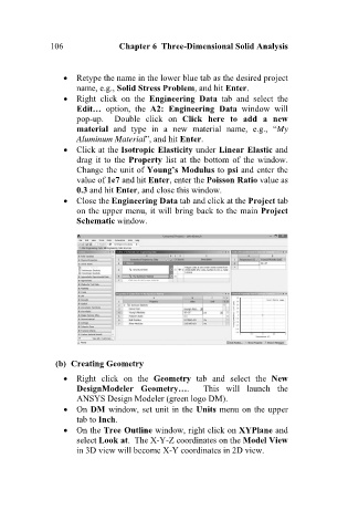
Right click on the Engineering Data tab and select the
Edit… option, the A2: Engineering Data window will
pop-up. Double click on Click here to add a new
material and type in a new material name, e.g., “My
Aluminum Material”, and hit Enter.
Click at the Isotropic Elasticity under Linear Elastic and
drag it to the Property list at the bottom of the window.
Change the unit of Young’s Modulus to psi and enter the
value of 1e7 and hit Enter, enter the Poisson Ratio value as
0.3 and hit Enter, and close this window.
Close the Engineering Data tab and click at the Project tab
on the upper menu, it will bring back to the main Project
Schematic window.
(b) Creating Geometry
Right click on the Geometry tab and select the New
DesignModeler Geometry…. This will launch the
ANSYS Design Modeler (green logo DM).
On DM window, set unit in the Units menu on the upper
tab to Inch.
On the Tree Outline window, right click on XYPlane and
select Look at. The X-Y-Z coordinates on the Model View
in 3D view will become X-Y coordinates in 2D view.