
Page 118 - Finite Element Analysis with ANSYS Workbench
P. 118
6.3 Academic Example 109
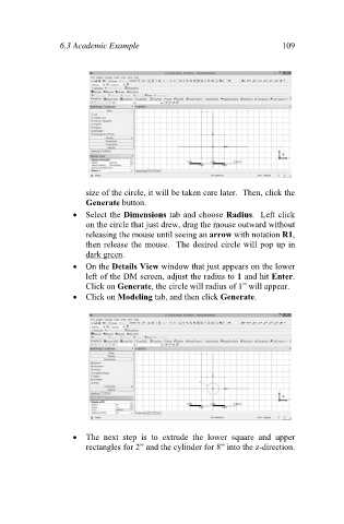
size of the circle, it will be taken care later. Then, click the
Generate button.
Select the Dimensions tab and choose Radius. Left click
on the circle that just drew, drag the mouse outward without
releasing the mouse until seeing an arrow with notation R1,
then release the mouse. The desired circle will pop up in
dark green.
On the Details View window that just appears on the lower
left of the DM screen, adjust the radius to 1 and hit Enter.
Click on Generate, the circle will radius of 1” will appear.
Click on Modeling tab, and then click Generate.
The next step is to extrude the lower square and upper
rectangles for 2” and the cylinder for 8” into the z-direction.