
Page 117 - Finite Element Analysis with ANSYS Workbench
P. 117
108 Chapter 6 Three-Dimensional Solid Analysis
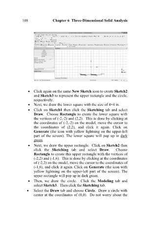
Click again on the same New Sketch icon to create Sketch2
and Sketch3 to represent the upper rectangle and the circle,
respectively.
Next, we draw the lower square with the size of 4×4 in.
Click on Sketch1 then click the Sketching tab and select
Draw. Choose Rectangle to create the lower square with
the vertices of (-2,-2) and (2,2). This is done by clicking at
the coordinates of (-2,-2) on the model, move the cursor to
the coordinates of (2,2), and click it again. Click on
Generate (the icon with yellow lightning on the upper-left
part of the screen). The lower square will pop up in dark
green.
Next, we draw the upper rectangle. Click on Sketch2 then
click the Sketching tab and select Draw. Choose
Rectangle to create this upper rectangle with the vertices of
(-2,2) and (-1,6). This is done by clicking at the coordinates
of (-2,2) on the model, move the cursor to the coordinates of
(-1,6), and click it again. Click on Generate (the icon with
yellow lightning on the upper-left part of the screen). The
upper rectangle will pop up in dark green.
Then, we draw the circle. Click the Modeling tab and
select Sketch3. Then click the Sketching tab.
Select the Draw tab and choose Circle. Draw a circle with
center at the coordinates of (0,0). Do not worry about the