
Page 119 - Finite Element Analysis with ANSYS Workbench
P. 119
110 Chapter 6 Three-Dimensional Solid Analysis
Click on the ISO tab on the upper menu bar so that the
model is shown in isometric view
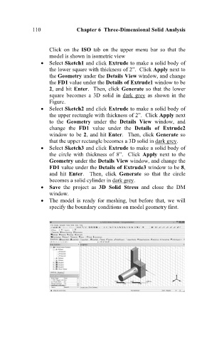
Select Sketch1 and click Extrude to make a solid body of
the lower square with thickness of 2”. Click Apply next to
the Geometry under the Details View window, and change
the FD1 value under the Details of Extrude1 window to be
2, and hit Enter. Then, click Generate so that the lower
square becomes a 3D solid in dark grey as shown in the
Figure.
Select Sketch2 and click Extrude to make a solid body of
the upper rectangle with thickness of 2”. Click Apply next
to the Geometry under the Details View window, and
change the FD1 value under the Details of Extrude2
window to be 2, and hit Enter. Then, click Generate so
that the upper rectangle becomes a 3D solid in dark grey.
Select Sketch3 and click Extrude to make a solid body of
the circle with thickness of 8”. Click Apply next to the
Geometry under the Details View window, and change the
FD1 value under the Details of Extrude3 window to be 8,
and hit Enter. Then, click Generate so that the circle
becomes a solid cylinder in dark grey.
Save the project as 3D Solid Stress and close the DM
window.
The model is ready for meshing, but before that, we will
specify the boundary conditions on model geometry first.