
Page 18 - Finite Element Analysis with ANSYS Workbench
P. 18
1.3 ANSYS Software 9
The project schematic region on the right side of the
screen is the working area. This larger region is for the user to
view what is happening at different stages starting from creating
geometry domain, discretizing domain into a number of small
elements, applying boundary conditions, solving for solutions and
displaying results.
1.3.3 Analyzing steps
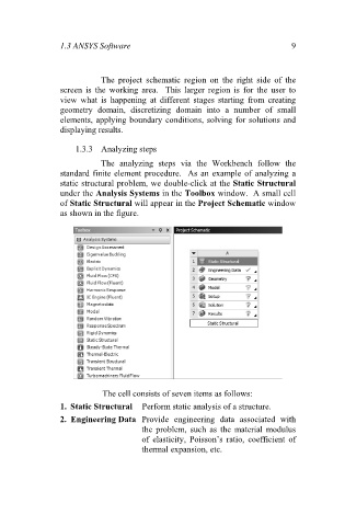
The analyzing steps via the Workbench follow the
standard finite element procedure. As an example of analyzing a
static structural problem, we double-click at the Static Structural
under the Analysis Systems in the Toolbox window. A small cell
of Static Structural will appear in the Project Schematic window
as shown in the figure.
The cell consists of seven items as follows:
1. Static Structural Perform static analysis of a structure.
2. Engineering Data Provide engineering data associated with
the problem, such as the material modulus
of elasticity, Poisson’s ratio, coefficient of
thermal expansion, etc.