
Page 58 - Finite Element Analysis with ANSYS Workbench
P. 58
3.3 Academic Example 49
the model, move the cursor to the coordinates of (1,0), and
click the mouse again. Then, follow the same procedure to
create the second line with the end coordinates of (0,1) and
(1,0). Click on Generate (the icon with yellow lightning on
the upper-left part of the screen). The desired two lines will
become dark green.
The next important step is to go to the Concept tab on top
of the screen and select Lines From Sketches.
Select the Sketch1, the two lines will become yellow.
Click Apply icon on the right side of the Base Objects tab
in the Details View at the lower left of the screen. Both
two lines will become cyan. Then, click on Generate. The
right side of the Base Objects tab will show 1 Sketch. The
1 Part, 1 Body item will appear in the Tree Outline
window.
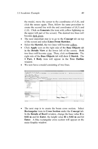
We now have a model consisting of two lines.
The next step is to create the beam cross section. Select
Rectangular item in Cross Section under the Concept tab.
In the Details of Rect1 window, change the base value B to
0.02 m and hit Enter, the height value H to 0.02 m and hit
Enter. A blue rectangular cross section will appear on the
main Graphic window.