
Page 56 - Finite Element Analysis with ANSYS Workbench
P. 56
3.3 Academic Example 47
(b) Creating Geometry
Right click on the Geometry tab and select the Properties
option, the Properties of Schematic window will open.
Select the Line Bodies under the Basic Geometry Options.
Then, close this small window.
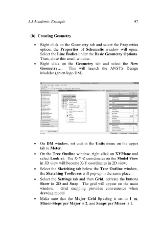
Right click on the Geometry tab and select the New
Geometry…. This will launch the ANSYS Design
Modeler (green logo DM).
On DM window, set unit in the Units menu on the upper
tab to Meter.
On the Tree Outline window, right click on XYPlane and
select Look at. The X-Y-Z coordinates on the Model View
in 3D view will become X-Y coordinates in 2D view.
Select the Sketching tab below the Tree Outline window,
the Sketching Toolboxes will pop-up in the same place.
Select the Settings tab and then Grid, activate the buttons
Show in 2D and Snap. The grid will appear on the main
window. Grid snapping provides convenience when
drawing model.
Make sure that the Major Grid Spacing is set to 1 m,
Minor-Steps per Major is 2, and Snaps per Minor is 1.