
Page 98 - Finite Element Analysis with ANSYS Workbench
P. 98
5.3 Academic Example 89
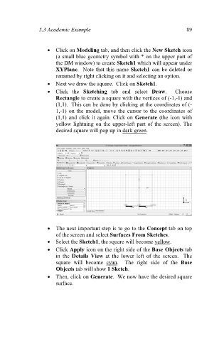
Click on Modeling tab, and then click the New Sketch icon
(a small blue geometry symbol with * on the upper part of
the DM window) to create Sketch1 which will appear under
XYPlane. Note that this name Sketch1 can be deleted or
renamed by right clicking on it and selecting an option.
Next we draw the square. Click on Sketch1.
Click the Sketching tab and select Draw. Choose
Rectangle to create a square with the vertices of (-1,-1) and
(1,1). This can be done by clicking at the coordinates of (-
1,-1) on the model, move the cursor to the coordinates of
(1,1) and click it again. Click on Generate (the icon with
yellow lightning on the upper-left part of the screen). The
desired square will pop up in dark green.
The next important step is to go to the Concept tab on top
of the screen and select Surfaces From Sketches.
Select the Sketch1, the square will become yellow.
Click Apply icon on the right side of the Base Objects tab
in the Details View at the lower left of the screen. The
square will become cyan. The right side of the Base
Objects tab will show 1 Sketch.
Then, click on Generate. We now have the desired square
surface.