
Page 99 - Finite Element Analysis with ANSYS Workbench
P. 99
90 Chapter 5 Plate Bending analysis
Click SurfaceSk1 and change the value of Thickness in the
Details View window to 0.01 and hit Enter.
Click ISO tab and Zoom tab on the upper menu bar so that
the model is displayed in three dimensions.
Save file as Simply-supported Plate, and close the DM
window.
(c) Assigning Material Properties and Creating Mesh
On the main Project Schematic window, double click on
Model, the thin plate model will appear back on the main
window.
Double click on Geometry item, the Surface Body item
will pop-up. Select the Surface Body item and select “My
Plate Material” (the name assigned earlier containing
material properties of this problem) which is on the right-
hand-side of Assignment under Material in Details of
“Surface Body” window. The plate model will become
green.
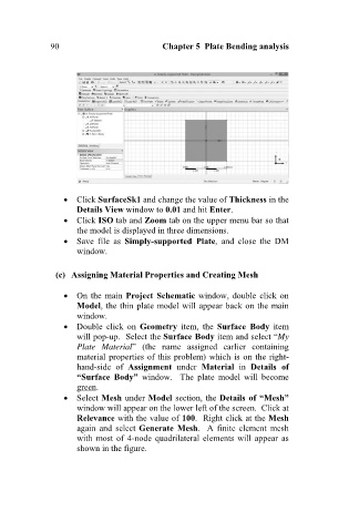
Select Mesh under Model section, the Details of “Mesh”
window will appear on the lower left of the screen. Click at
Relevance with the value of 100. Right click at the Mesh
again and select Generate Mesh. A finite element mesh
with most of 4-node quadrilateral elements will appear as
shown in the figure.