
Page 127 - Finite Element Modeling and Simulations with ANSYS Workbench
P. 127
112 Finite Element Modeling and Simulation with ANSYS Workbench
3.7 Summary
This chapter is devoted to the beam element and frame analysis. We have studied the
beam element, which can be used in frame analysis. The concept of the shape functions is
further explored and the derivations of the stiffness matrix using the energy approach are
emphasized. Treatment of distributed loads is discussed and several examples are stud-
ied. A two-story building structure with I-beams is analyzed using ANSYS Workbench.
It provides useful modeling techniques in constructing concept line models, and shows
step-by-step how Workbench can be used to determine the deformation and stresses in
beams and frames.
3.8 Review of Learning Objectives
Now that you have finished this chapter, you should be able to
1. Set up simplified finite element models for beams and frames.
2. Derive the element stiffness matrix for plane beams using direct/energy approach.
3. Explain the concept of shape functions and their characteristics for beam elements.
4. Find the equivalent nodal forces of distributed loads on beams.
5. Determine the deflection and rotation at a point of a beam using hand calculation
to verify the finite element solutions.
6. Apply the general beam element stiffness matrix to the analysis of simple frames.
7. Create line models from concept points, sketches, or by body translation in
Workbench.
8. Perform static structural analyses on beams and frames using Workbench.
PROBLEMS
3.1 Using Equation 3.11, derive the results of the equivalent nodal forces and
moments for a beam element with uniformly distributed lateral load.
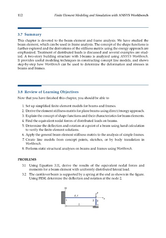
3.2 The cantilever beam is supported by a spring at the end as shown in the figure.
Using FEM, determine the deflection and rotation at the node 2.
y
P
E, I
1 2 k x
L 3