
Page 129 - Finite Element Modeling and Simulations with ANSYS Workbench
P. 129
114 Finite Element Modeling and Simulation with ANSYS Workbench
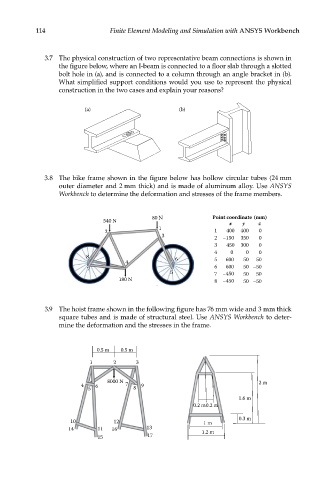
3.7 The physical construction of two representative beam connections is shown in
the figure below, where an I-beam is connected to a floor slab through a slotted
bolt hole in (a), and is connected to a column through an angle bracket in (b).
What simplified support conditions would you use to represent the physical
construction in the two cases and explain your reasons?
(a) (b)
3.8 The bike frame shown in the figure below has hollow circular tubes (24 mm
outer diameter and 2 mm thick) and is made of aluminum alloy. Use ANSYS
Workbench to determine the deformation and stresses of the frame members.
80 N Point coordinate (mm)
540 N x y z
1
2 1 400 400 0
3 2 –150 350 0
3 450 300 0
4 0 0 0
8 6 5 600 50 50
4
7 6 600 50 –50
5 7 –450 50 50
180 N 8 –450 50 –50
3.9 The hoist frame shown in the following figure has 76 mm wide and 3 mm thick
square tubes and is made of structural steel. Use ANSYS Workbench to deter-
mine the deformation and the stresses in the frame.
0.5 m 0.5 m
1 2 3
8000 N 2 m
4 6 7 9
5 8
1.6 m
0.2 m0.2 m
0.3 m
10 12 1 m
14 11 16 13 1.2 m
15 17