
Page 128 - Finite Element Modeling and Simulations with ANSYS Workbench
P. 128
Beams and Frames 113
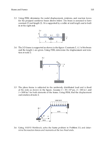
3.3 Using FEM, determine the nodal displacement, rotations, and reaction forces
for the propped cantilever beam shown below. The beam is assumed to have
constant EI and length 2L. It is supported by a roller at mid length and is built
in at the right end.
Y
P
1 E, I 2
1 2 3 X
L L
3.4 The 2-D frame is supported as shown in the figure. Constants E, A, I of the beam
and the length L are given. Using FEM, determine the displacement and rota-
tion at node 2.
Y
M
1 L 2 X
L
3
3.5 The plane frame is subjected to the uniformly distributed load and is fixed
at the ends as shown in the figure. Assume E = 30 × 10 psi, A = 100 in. , and
2
6
I = 1000 in. for both elements of the frame. Using FEM, find the displacement
4
and rotation of node 2.
1000 lb/ft
2 3
Y
40 ft
45° X
1
30 ft
3.6 Using ANSYS Workbench, solve the frame problem in Problem 3.5, and deter-
mine the reaction forces and moments at the two fixed ends.