
Page 133 - Finite Element Modeling and Simulations with ANSYS Workbench
P. 133
118 Finite Element Modeling and Simulation with ANSYS Workbench
(a) (b)
River
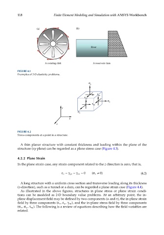
A rotating disk A reservoir dam
FIGURE 4.1
Examples of 2-D elasticity problems.
y
xy
yz
x
zx
y
z
x
z
FIGURE 4.2
Stress components at a point in a structure.
A thin planar structure with constant thickness and loading within the plane of the
structure (xy-plane) can be regarded as a plane stress case (Figure 4.3).
4.2.2 Plane Strain
In the plane strain case, any strain component related to the z direction is zero, that is,
= 0 ( σ≠ 0) (4.2)
z
ε= γ yz = γ zx z
A long structure with a uniform cross section and transverse loading along its thickness
(z-direction), such as a tunnel or a dam, can be regarded a plane strain case (Figure 4.4).
As illustrated in the above figures, structures in plane stress or plane strain condi-
tions can be modeled as 2-D boundary value problems. At an arbitrary point, the in-
plane displacement field may be defined by two components (u and v), the in-plane strain
field by three components (ε x , ε y , γ xy ), and the in-plane stress field by three components
(σ x , σ y , τ xy ). The following is a review of equations describing how the field variables are
related.