
Page 137 - Finite Element Modeling and Simulations with ANSYS Workbench
P. 137
122 Finite Element Modeling and Simulation with ANSYS Workbench
should deform in a continuous manner, with no cracks or overlaps in the obtained dis-
placement fields).
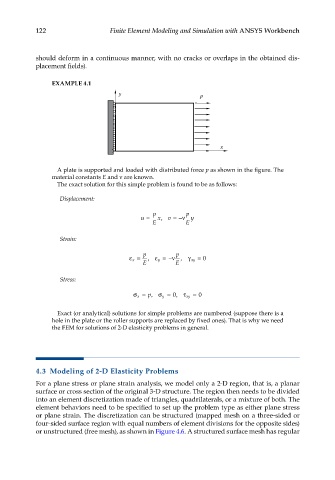
EXAMPLE 4.1
y p
x
A plate is supported and loaded with distributed force p as shown in the figure. The
material constants E and ν are known.
The exact solution for this simple problem is found to be as follows:
Displacement:
p p
u = x, v = −ν y
E E
Strain:
p p
ε x = , ε y = −ν , γ xy = 0
E E
Stress:
0
σ= p, σ= , τ xy = 0
x
y
Exact (or analytical) solutions for simple problems are numbered (suppose there is a
hole in the plate or the roller supports are replaced by fixed ones). That is why we need
the FEM for solutions of 2-D elasticity problems in general.
4.3 Modeling of 2-D Elasticity Problems
For a plane stress or plane strain analysis, we model only a 2-D region, that is, a planar
surface or cross section of the original 3-D structure. The region then needs to be divided
into an element discretization made of triangles, quadrilaterals, or a mixture of both. The
element behaviors need to be specified to set up the problem type as either plane stress
or plane strain. The discretization can be structured (mapped mesh on a three-sided or
four-sided surface region with equal numbers of element divisions for the opposite sides)
or unstructured (free mesh), as shown in Figure 4.6. A structured surface mesh has regular