
Page 138 - Finite Element Modeling and Simulations with ANSYS Workbench
P. 138
Two-Dimensional Elasticity 123
(a) (b)
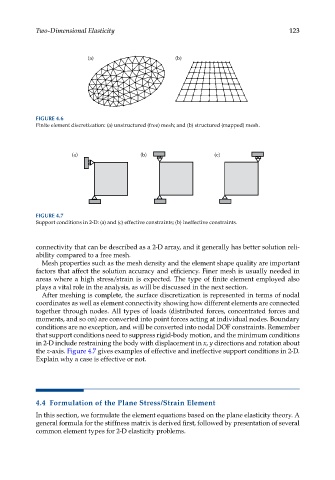
FIGURE 4.6
Finite element discretization: (a) unstructured (free) mesh; and (b) structured (mapped) mesh.
(a) (b) (c)
FIGURE 4.7
Support conditions in 2-D: (a) and (c) effective constraints; (b) ineffective constraints.
connectivity that can be described as a 2-D array, and it generally has better solution reli-
ability compared to a free mesh.
Mesh properties such as the mesh density and the element shape quality are important
factors that affect the solution accuracy and efficiency. Finer mesh is usually needed in
areas where a high stress/strain is expected. The type of finite element employed also
plays a vital role in the analysis, as will be discussed in the next section.
After meshing is complete, the surface discretization is represented in terms of nodal
coordinates as well as element connectivity showing how different elements are connected
together through nodes. All types of loads (distributed forces, concentrated forces and
moments, and so on) are converted into point forces acting at individual nodes. Boundary
conditions are no exception, and will be converted into nodal DOF constraints. Remember
that support conditions need to suppress rigid-body motion, and the minimum conditions
in 2-D include restraining the body with displacement in x, y directions and rotation about
the z-axis. Figure 4.7 gives examples of effective and ineffective support conditions in 2-D.
Explain why a case is effective or not.
4.4 Formulation of the Plane Stress/Strain Element
In this section, we formulate the element equations based on the plane elasticity theory. A
general formula for the stiffness matrix is derived first, followed by presentation of several
common element types for 2-D elasticity problems.