Page 136 - Finite Element Modeling and Simulations with ANSYS Workbench
P. 136

Two-Dimensional Elasticity                                                  121


              In matrix form, we write

                                    ε    ∂∂x    0  
                                           /
                                    x
                                                        u
                                                     
                                                                =
                                                  /
                                   ε  =    0  ∂∂y     ,  or  ε = Du              (4.8)
                                    y
                                                        v
                                        ∂∂y   ∂∂  x   
                                           /
                                                  /
                                    γ xy           
              From this relation, we know that, if the displacements are represented by polynomials,
            the strains (and thus stresses) will be polynomials of an order that is one order lower than
            the displacements.
            4.2.5  Equilibrium Equations
            In plane elasticity, the stresses in the structure must satisfy the following equilibrium
            equations:
                                           ∂σ x  +  ∂τ xy  + f  = 0
                                           ∂x    ∂y     x
                                                                                        (4.9)
                                           ∂τ xy  +  ∂σ y  + f  = 0
                                            ∂x    ∂y    y

            where f  and f  are body forces (forces per unit volume, such as gravity forces). In the FEM,
                  x
                        y
            these equilibrium conditions are satisfied in an approximate sense.
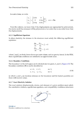
            4.2.6  Boundary Conditions
            The boundary S of the 2-D region can be divided into two parts, S  and S  (Figure 4.5). The
                                                                            t
                                                                      u
            boundary conditions (BCs) can be described as
                                      u =  u,  v =  v,      on  S u
                                      t x =  t x ,  t y =  t y ,  on  S t              (4.10)


            in which t  and t  are tractions (stresses on the boundary) and the barred quantities are
                     x
                           y
            those with known values.
            4.2.7  Exact Elasticity Solution

            The exact solution (displacements, strains, and stresses) of a given problem must satisfy
            the constitutive relations, equilibrium equations, and compatibility conditions (structures


                                                           t y
                                               p
                                                              t x
                                         y
                                          S t
                                                      S u
                                                 x

            FIGURE 4.5
            Boundary conditions for a structure.
   131   132   133   134   135   136   137   138   139   140   141