
Page 142 - Finite Element Modeling and Simulations with ANSYS Workbench
P. 142
Two-Dimensional Elasticity 127
= 0
= 0 = b
3
= a = 1
A 1
= 1 A 2 (a, b)
2
1
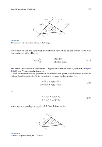
FIGURE 4.9
The natural coordinate system defined on the triangle.
which ensures that the rigid-body translation is represented by the chosen shape func-
tions. Also, as in the 1-D case,
i
1, atnode ;
N i = (4.23)
0, at other nodes
and varies linearly within the element. The plot for shape function N is shown in Figure
1
4.10. N and N have similar features.
2
3
We have two coordinate systems for the element: the global coordinates (x, y) and the
natural (local) coordinates (ξ, η). The relation between the two is given by
x = N x + N x + N x
33
11
22
y = N y + N y + N y (4.24)
11 22 33
or,
x = x ξ + x η + x 3
13
23
y = y ξ + y η + (4.25)
13 23 y 3
where x = x − x and y = y − y (i, j = 1, 2, 3) as defined earlier.
j
i
i
j
ij
ij
= 0
3
N 1
= 1
1
2
1
FIGURE 4.10
Plot of the shape function N 1 for T3 element.