
Page 145 - Finite Element Modeling and Simulations with ANSYS Workbench
P. 145
130 Finite Element Modeling and Simulation with ANSYS Workbench
= 0
3
= 1/2
6 5
= 1 N
1 1
4 2
1
FIGURE 4.12
Plot of the shape function N 1 for T6 element.
Displacements can be written as
6
6
u = ∑ N u , v = ∑ Nv (4.34)
ii
ii
i=1 i=1
T
B EB dV, but here B EB is quadratic
T
The element stiffness matrix is still given by k =∫ V
in x and y. In general, the integral has to be computed numerically.
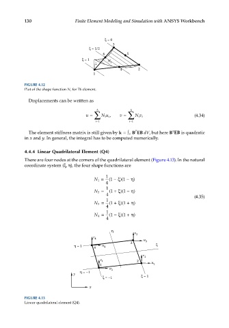
4.4.4 Linear Quadrilateral Element (Q4)
There are four nodes at the corners of the quadrilateral element (Figure 4.13). In the natural
coordinate system (ξ, η), the four shape functions are
1
N 1 = ( 1 − ξ)( 1 − η)
4
1
N 2 = ( 1 + ξ)( 1 − η)
4 (4.35)
1
N 3 = ( 1 + ξ)( 1 + η)
4
1
η
N 4 = ( 1 − ξ)( 1 + η)
4
v
v 4 3
3 u 3
= 1 4 u 4
v 2
v 1 2
1 u 2
u 1
y = –1
= –1 = 1
x
FIGURE 4.13
Linear quadrilateral element (Q4).