
Page 147 - Finite Element Modeling and Simulations with ANSYS Workbench
P. 147
132 Finite Element Modeling and Simulation with ANSYS Workbench
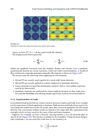
FIGURE 4.15
Analysis of composite materials (mesh and contour stress plots).
8
Again, we have ∑ =i N i = 1 at any point inside the element.
1
The displacement field is given by
8
8
u = ∑ N u , v = ∑ Nv (4.38)
ii
ii
i=1 i=1
which are quadratic functions over the element. Strains and stresses over a quadratic
quadrilateral element are linear functions, which are better representations. A model of
fiber-reinforced composite materials using the Q8 elements is shown in Figure 4.15.
We need to note the following when applying the 2-D elements:
• Q4 and T3 are usually used together in a mesh with linear elements.
• Q8 and T6 are usually applied in a mesh composed of quadratic elements.
• Linear elements are good for deformation analysis, that is, when global responses
need to be determined.
• Quadratic elements are preferred for stress analysis, because of their high accu-
racy and the flexibility in modeling complex geometry, such as curved boundaries.
4.4.6 Transformation of Loads
Concentrated load (point forces), surface traction (pressure loads), and body force (weight)
are the main types of loads applied to a structure. Both traction and body forces need to be
converted into nodal forces in the FE model, since they cannot be applied to the FE model
directly. The conversions of these loads are based on the same idea (the equivalent-work
concept), which we have used for the cases of bar and beam elements.
Suppose, for example, we have a linearly varying traction q on a Q4 element edge, as
shown in the Figure 4.16. The traction is normal to the boundary. Using the local (tangen-
tial) coordinate s, we can write the work done by the traction q as
L
∫
1
W q = t us qs ds
()
()
n
2
0