
Page 151 - Finite Element Modeling and Simulations with ANSYS Workbench
P. 151
136 Finite Element Modeling and Simulation with ANSYS Workbench
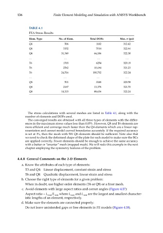
TABLE 4.1
FEA Stress Results
Elem. Type No. of Elem. Total DOFs Max. σ (psi)
Q4 506 1102 312.42
Q4 3352 7014 322.64
Q4 31,349 64,106 322.38
... ... ... ...
T6 1518 6254 320.18
T6 2562 10,494 321.23
T6 24,516 100,702 322.24
... ... ... ...
Q8 501 3188 320.58
Q8 2167 13,376 321.70
Q8 14,333 88,636 322.24
The stress calculations with several meshes are listed in Table 4.1, along with the
number of elements and DOFs used.
The converged results are obtained with all three types of elements with the differ-
ences in the maximum stress values less than 0.05%. However, Q8 and T6 elements are
more efficient and converge much faster than the Q4 elements which are a linear rep-
resentation and cannot model curved boundaries accurately. If the required accuracy
is set at 1%, then the mesh with 501 Q8 elements should be sufficient. Note also that
we need to check the deformed shape of the plate for each model to make sure the BCs
are applied correctly. Fewer elements should be enough to achieve the same accuracy
with a better or “smarter” mesh (mapped mesh). We will redo this example in the next
chapter employing the symmetry features of the problem.
4.4.8 General Comments on the 2-D Elements
a. Know the attributes of each type of elements:
T3 and Q4: Linear displacement, constant strain and stress
T6 and Q8: Quadratic displacement, linear strain and stress
b. Choose the right type of elements for a given problem:
When in doubt, use higher order elements (T6 or Q8) or a finer mesh.
c. Avoid elements with large aspect ratios and corner angles (Figure 4.17):
Aspect ratio = L max /L min where L max and L min are the largest and smallest character-
istic lengths of an element, respectively.
d. Make sure the elements are connected properly:
Do not leave unintended gaps or free elements in FE models (Figure 4.18).