
Page 177 - Finite Element Modeling and Simulations with ANSYS Workbench
P. 177
162 Finite Element Modeling and Simulation with ANSYS Workbench
FIGURE 5.1
Some examples of symmetry: (a) reflective symmetry (From http://www.thinkingfountain.org/s/ symmetry/
butterflypattern.gif); (b) axisymmetry; (c) rotational symmetry (From http://csdt.rpi.edu/na/pnwb/
symmetry2a.html); and (d) translational symmetry (From http://library.thinkquest.org/16661/background/
symmetry.1.html).
5.2.1 An Example
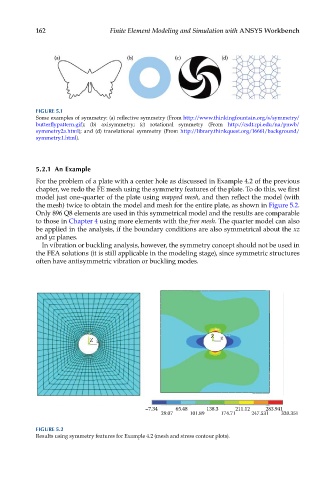
For the problem of a plate with a center hole as discussed in Example 4.2 of the previous
chapter, we redo the FE mesh using the symmetry features of the plate. To do this, we first
model just one-quarter of the plate using mapped mesh, and then reflect the model (with
the mesh) twice to obtain the model and mesh for the entire plate, as shown in Figure 5.2.
Only 896 Q8 elements are used in this symmetrical model and the results are comparable
to those in Chapter 4 using more elements with the free mesh. The quarter model can also
be applied in the analysis, if the boundary conditions are also symmetrical about the xz
and yz planes.
In vibration or buckling analysis, however, the symmetry concept should not be used in
the FEA solutions (it is still applicable in the modeling stage), since symmetric structures
often have antisymmetric vibration or buckling modes.
Z
Z
–7.34 65.48 138.3 211.12 283.941
29.07 101.89 174.71 247.531 320.351
FIGURE 5.2
Results using symmetry features for Example 4.2 (mesh and stress contour plots).