
Page 297 - Finite Element Modeling and Simulations with ANSYS Workbench
P. 297
282 Finite Element Modeling and Simulation with ANSYS Workbench
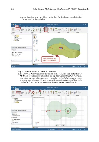
along y-direction, and type 50mm in the box for depth. An extruded solid
body is created as shown below.
Step 8: Create an Extruded Cut on the Top Face
In the Graphics Window, click on the top face of the solid, and click on the Sketch
Mode icon to place the sketch grid on the top face. Click on the Plan View icon
to create a top view of the geometry. Next, click on the Point icon, and create
a point O that is located 170mm horizontally to the left of point A. Then click
on the Circle icon, and draw a circle of diameter 45mm centered at point O.