
Page 293 - Finite Element Modeling and Simulations with ANSYS Workbench
P. 293
278 Finite Element Modeling and Simulation with ANSYS Workbench
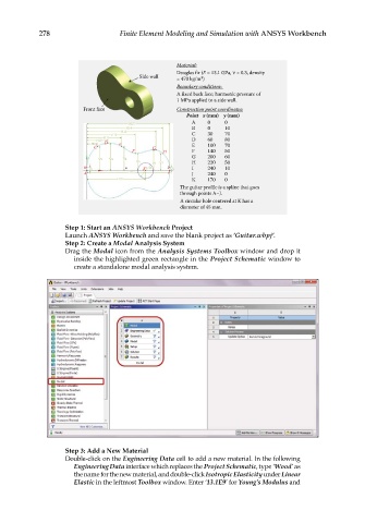
Material:
Douglas fir (E = 13.1 GPa, = 0.3, density
Side wall 3
= 470 kg/m )
Boundary conditions:
A fixed back face; harmonic pressure of
1 MPa applied to a side wall.
Front face Construction point coordinates:
Point x (mm) y (mm)
A 0 0
H15
H14 B 0 10
H13
H12 C 30 70
H11
H10 D 60 80
H9 D E E 100 70
C G
F H F 140 50
G 200 60
V2 V3 V4
V5 V6 V7 H 220 50
B V1 K D18 I V8 I 240 10
A H16 J J 240 0
H17 K 170 0
The guitar profile is a spline that goes
through points A–J.
A circular hole centered at K has a
diameter of 45 mm.
Step 1: Start an ANSYS Workbench Project
Launch ANSYS Workbench and save the blank project as ‘Guitar.wbpj’.
Step 2: Create a Modal Analysis System
Drag the Modal icon from the Analysis Systems Toolbox window and drop it
inside the highlighted green rectangle in the Project Schematic window to
create a standalone modal analysis system.
Step 3: Add a New Material
Double-click on the Engineering Data cell to add a new material. In the following
Engineering Data interface which replaces the Project Schematic, type ‘Wood’ as
the name for the new material, and double-click Isotropic Elasticity under Linear
Elastic in the leftmost Toolbox window. Enter ‘13.1E9’ for Young’s Modulus and