
Page 291 - Finite Element Modeling and Simulations with ANSYS Workbench
P. 291
276 Finite Element Modeling and Simulation with ANSYS Workbench
FIGURE 8.11
The first vibration mode of the bumper.
8.6.2 Frequency Response Analysis
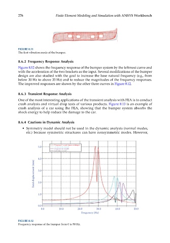
Figure 8.12 shows the frequency response of the bumper system by the leftmost curve and
with the acceleration of the two brackets as the input. Several modifications of the bumper
design are also studied with the goal to increase the base natural frequency (e.g., from
below 30 Hz to above 35 Hz) and to reduce the magnitudes of the frequency responses.
The improved responses are shown by the other three curves in Figure 8.12.
8.6.3 Transient Response Analysis
One of the most interesting applications of the transient analysis with FEA is to conduct
crash analysis and virtual drop tests of various products. Figure 8.13 is an example of
crash analysis of a car using the FEA, showing that the bumper system absorbs the
shock energy to help reduce the damage to the car.
8.6.4 Cautions in Dynamic Analysis
• Symmetry model should not be used in the dynamic analysis (normal modes,
etc.) because symmetric structures can have nonsymmetric modes. However,
Proposed I model (current design)
5.0 Proposed III model
Proposed III model
Reference model
4.0
Total displacement (mm) 3.0
2.0
1.0
0.0
0.0 10.0 20.0 30.0 40.0 50.0
Frequency (Hz)
FIGURE 8.12
Frequency response of the bumper from 0 to 50 Hz.