
Page 299 - Finite Element Modeling and Simulations with ANSYS Workbench
P. 299
284 Finite Element Modeling and Simulation with ANSYS Workbench
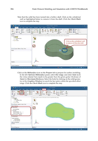
Note that the solid has been turned into a hollow shell. Click on the cylindrical
wall as highlighted below to remove it from the shell. Click the Check Mark
icon to complete the step.
Click on the Midsurface icon on the Prepare tab to prepare for surface modeling.
In the left Options-Midsurface panel, select Use range, and enter 5mm (note
the value entered here needs to be greater than the given guitar thickness of
3mm) for Maximum thickness. Select the body by clicking on the solid geome-
try in the Graphics Window to search for face pairs within the specified offset
range. Click the Check Mark icon to complete the step.