
Page 30 - Finite Element Modeling and Simulations with ANSYS Workbench
P. 30
Introduction 15
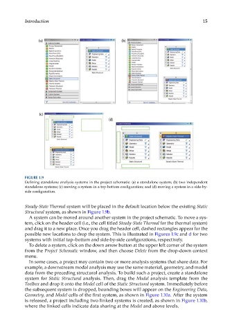
FIGURE 1.9
Defining standalone analysis systems in the project schematic: (a) a standalone system; (b) two independent
standalone systems; (c) moving a system in a top-bottom configuration; and (d) moving a system in a side-by-
side configuration.
Steady-State Thermal system will be placed in the default location below the existing Static
Structural system, as shown in Figure 1.9b.
A system can be moved around another system in the project schematic. To move a sys-
tem, click on the header cell (i.e., the cell titled Steady-State Thermal for the thermal system)
and drag it to a new place. Once you drag the header cell, dashed rectangles appear for the
possible new locations to drop the system. This is illustrated in Figures 1.9c and d for two
systems with initial top–bottom and side-by-side configurations, respectively.
To delete a system, click on the down arrow button at the upper left corner of the system
from the Project Schematic window, and then choose Delete from the drop-down context
menu.
In some cases, a project may contain two or more analysis systems that share data. For
example, a downstream modal analysis may use the same material, geometry, and model
data from the preceding structural analysis. To build such a project, create a standalone
system for Static Structural analysis. Then, drag the Modal analysis template from the
Toolbox and drop it onto the Model cell of the Static Structural system. Immediately before
the subsequent system is dropped, bounding boxes will appear on the Engineering Data,
Geometry, and Model cells of the first system, as shown in Figure 1.10a. After the system
is released, a project including two linked systems is created, as shown in Figure 1.10b,
where the linked cells indicate data sharing at the Model and above levels.