
Page 29 - Finite Element Modeling and Simulations with ANSYS Workbench
P. 29
14 Finite Element Modeling and Simulation with ANSYS Workbench
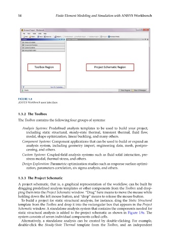
FIGURE 1.8
ANSYS Workbench user interface.
1.3.2 The Toolbox
The Toolbox contains the following four groups of systems:
Analysis Systems: Predefined analysis templates to be used to build your project,
including static structural, steady-state thermal, transient thermal, fluid flow,
modal, shape optimization, linear buckling, and many others.
Component Systems: Component applications that can be used to build or expand an
analysis system, including geometry import, engineering data, mesh, postpro-
cessing, and others.
Custom Systems: Coupled-field analysis systems such as fluid solid interaction, pre-
stress modal, thermal-stress, and others.
Design Exploration: Parametric optimization studies such as response surface optimi-
zation, parameters correlation, six sigma analysis, and others.
1.3.3 The Project Schematic
A project schematic, that is, a graphical representation of the workflow, can be built by
dragging predefined analysis templates or other components from the Toolbox and drop-
ping them into the Project Schematic window. “Drag” here means to move the mouse while
holding down the left mouse button, and “drop” means to release the mouse button.
To build a project for static structural analysis, for instance, drag the Static Structural
template from the Toolbox and drop it into the rectangular box that appears in the Project
Schematic window. A standalone analysis system that contains the components needed for
static structural analysis is added to the project schematic as shown in Figure 1.9a. The
system consists of seven individual components called cells.
Alternatively, a standalone analysis can be created by double-clicking. For example,
double-click the Steady-State Thermal template from the Toolbox, and an independent