
Page 28 - Finite Element Modeling and Simulations with ANSYS Workbench
P. 28
Introduction 13
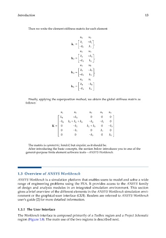
Then we write the element stiffness matrix for each element
u 4 u 2
k 1 − k 1
1 k = ,
− k 1 k 1
u 2 u 3
k 2 − k 2
2 k = ,
− k 2 k 2
u 3 u 5
k
k 3 −k 3
3 k = ,
− k 3 k 3
u 2 u 1
k 4 − k 4
k 4 = −
k 4 k 4
Finally, applying the superposition method, we obtain the global stiffness matrix as
follows:
u 1 u 2 u 3 u 4 u 5
k 4 − k 4 0 0 0
− k 4 k 1 + k 2 + k 4 − k 2 − k 1 0
K = 0 − k 2 k 2 + k 3 0 −
k 3
0 − k 1 0 k 1 0 0
0 0 −k 0 k
3 3
The matrix is symmetric, banded, but singular, as it should be.
After introducing the basic concepts, the section below introduces you to one of the
general-purpose finite element software tools—ANSYS Workbench.
1.3 Overview of ANSYS Workbench
ANSYS Workbench is a simulation platform that enables users to model and solve a wide
range of engineering problems using the FEA. It provides access to the ANSYS family
of design and analysis modules in an integrated simulation environment. This section
gives a brief overview of the different elements in the ANSYS Workbench simulation envi-
ronment or the graphical-user interface (GUI). Readers are referred to ANSYS Workbench
user’s guide [2] for more detailed information.
1.3.1 The User Interface
The Workbench interface is composed primarily of a Toolbox region and a Project Schematic
region (Figure 1.8). The main use of the two regions is described next.