
Page 70 - Finite Element Modeling and Simulations with ANSYS Workbench
P. 70
Bars and Trusses 55
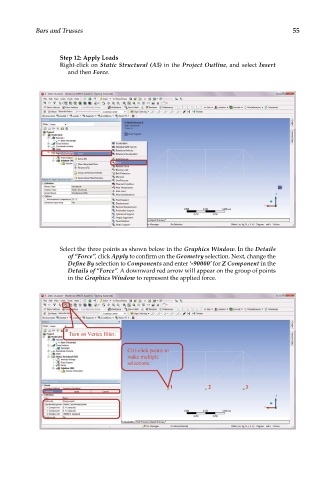
Step 12: Apply Loads
Right-click on Static Structural (A5) in the Project Outline, and select Insert
and then Force.
Select the three points as shown below in the Graphics Window. In the Details
of “Force”, click Apply to confirm on the Geometry selection. Next, change the
Define By selection to Components and enter ‘-90000’ for Z Component in the
Details of “Force”. A downward red arrow will appear on the group of points
in the Graphics Window to represent the applied force.