
Page 75 - Finite Element Modeling and Simulations with ANSYS Workbench
P. 75
60 Finite Element Modeling and Simulation with ANSYS Workbench
A 3A A 3A
P
A A
5L 2L 5L 2L
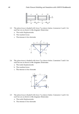
2.3 The plane truss is loaded with force P as shown below. Constants E and A for
each bar are as shown in the diagram. Determine:
a. The nodal displacements
b. The reaction forces
c. The stresses in bar elements
Y
L L
3 1 4
L E, A E, A E, A
2 X
P
2.4 The plane truss is loaded with force P as shown below. Constants E and A for
each bar are as shown in the diagram. Determine:
a. The nodal displacements
b. The reaction forces
c. The stresses in bar elements
Y L
4 3
E, A E, 2 2 A
L
45°
1 45° 2
E, A X
P
2.5 The plane truss is loaded with force P as shown below. Constants E and A for
each bar are as shown in the diagram. Determine:
a. The nodal displacements
b. The stresses in bar elements