
Page 77 - Finite Element Modeling and Simulations with ANSYS Workbench
P. 77
62 Finite Element Modeling and Simulation with ANSYS Workbench
Y
4
5A
L/2
2A 5 P
L/2 5A A 5A
1 X
2A 2 2A 3
L L
2.9 The roof truss shown below is made of Douglas fir timbers of a 5 mm × 5 mm
cross section. Use ANSYS Workbench to determine the truss deformation and
the support reaction forces.
1 kN
1 kN 1 kN 0.25 m
1 kN 1 kN 0.25 m
0.2 m
0.2 m 0.25 m 0.25 m 0.25 m 0.25 m 0.2 m
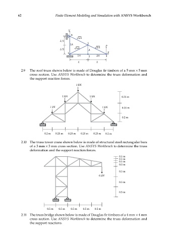
2.10 The truss tower crane shown below is made of structural steel rectangular bars
of a 3 mm × 3 mm cross section. Use ANSYS Workbench to determine the truss
deformation and the support reaction forces.
0.1 m
0.1 m
0.1 m
0.2 m
0.5 m
6 kN
0.5 m
0.5 m
0.5 m 0.5 m 0.5 m 0.5 m 0.5 m
2.11 The truss bridge shown below is made of Douglas fir timbers of a 4 mm × 4 mm
cross section. Use ANSYS Workbench to determine the truss deformation and
the support reactions.