
Page 74 - Finite Element Modeling and Simulations with ANSYS Workbench
P. 74
Bars and Trusses 59
2.7 Summary
In this chapter, we studied the bar elements which can be used in truss analysis. The con-
cept of the shape functions is introduced and the derivations of the stiffness matrices using
the energy approach are introduced. Treatment of distributed loads is discussed and sev-
eral examples are studied. A planar truss structure is analyzed using ANSYS Workbench.
It provides basic modeling techniques and shows step-by-step how Workbench can be used
to determine the deformation and reaction forces in trusses.
2.8 Review of Learning Objectives
Now that you have finished this chapter you should be able to
1. Set up simplified finite element models for truss structures.
2. Derive the stiffness matrix for plane bar elements using direct and energy
approaches.
3. Explain the concept of shape functions and their characteristics for bar elements.
4. Find the equivalent nodal loads of distributed forces on bars.
5. Determine the displacement and stress of a truss using hand calculation to verify
the finite element solutions.
6. Apply the general bar element stiffness matrix to the analysis of simple trusses.
7. Create line sketches and new material definition in ANSYS Workbench.
8. Perform static structural analyses on trusses using ANSYS Workbench.
PROBLEMS
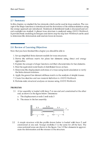
2.1 A bar assembly is loaded with force P at one end and constrained at the other
end, as shown in the figure below. Determine:
a. The displacement at node 2 and node 3
b. The stress in the bar assembly
E, 2A
E, A E, A
P
1 2 3 4
L L L
2.2 A simple structure with the profile shown below is loaded with force P, and
constrained at one end. Young’s modulus E is the same for all the bars. The
cross-sectional areas are shown in the figure. Use 1-D bar elements to approxi-
mate the deformation and the stresses in the structure.