
Page 76 - Finite Element Modeling and Simulations with ANSYS Workbench
P. 76
Bars and Trusses 61
Y
3
P
45° E, 22A
L
E, A
1 45° 2
E, A X
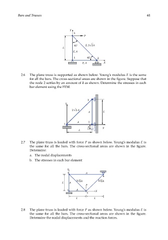
2.6 The plane truss is supported as shown below. Young’s modulus E is the same
for all the bars. The cross-sectional areas are shown in the figure. Suppose that
the node 2 settles by an amount of δ as shown. Determine the stresses in each
bar element using the FEM.
3
Y
22 A
A L
A 2
1
X
L
2.7 The plane truss is loaded with force P as shown below. Young’s modulus E is
the same for all the bars. The cross-sectional areas are shown in the figure.
Determine:
a. The nodal displacements
b. The stresses in each bar element
Y
3 A
4
2 2A 2 2A
L A
P
1 A X
2
L L
2.8 The plane truss is loaded with force P as shown below. Young’s modulus E is
the same for all the bars. The cross-sectional areas are shown in the figure.
Determine the nodal displacements and the reaction forces.