
Page 81 - Finite Element Modeling and Simulations with ANSYS Workbench
P. 81
66 Finite Element Modeling and Simulation with ANSYS Workbench
FIGURE 3.1
Examples of beams and frames: (a) a car frame (http://www.carbasics-1950.com/); and (b) an exercise machine.
(From http://www.nibbledaily.com/body-by-jake-cardio-cruiser/.)
Reference:
Deformed:
Euler–Bernoulli beam Timoshenko beam
FIGURE 3.2
Two common beam models.
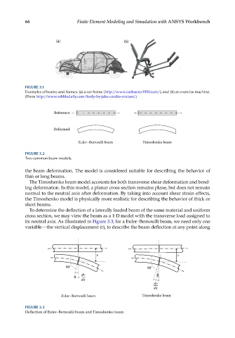
the beam deformation. The model is considered suitable for describing the behavior of
thin or long beams.
The Timoshenko beam model accounts for both transverse shear deformation and bend-
ing deformation. In this model, a planar cross section remains plane, but does not remain
normal to the neutral axis after deformation. By taking into account shear strain effects,
the Timoshenko model is physically more realistic for describing the behavior of thick or
short beams.
To determine the deflection of a laterally loaded beam of the same material and uniform
cross section, we may view the beam as a 1-D model with the transverse load assigned to
its neutral axis. As illustrated in Figure 3.3, for a Euler–Bernoulli beam, we need only one
variable—the vertical displacement (v), to describe the beam deflection at any point along
v v
90° 90°
dv
=
dx
dv
dx
Euler–Bernoulli beam Timoshenko beam
FIGURE 3.3
Deflection of Euler–Bernoulli beam and Timoshenko beam.