
Page 83 - Finite Element Modeling and Simulations with ANSYS Workbench
P. 83
68 Finite Element Modeling and Simulation with ANSYS Workbench
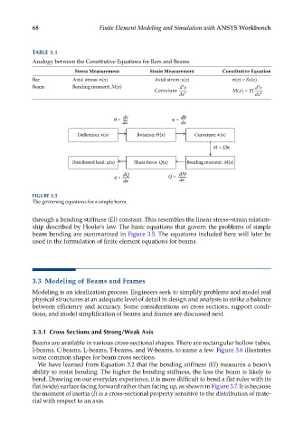
TABLE 3.1
Analogy between the Constitutive Equations for Bars and Beams
Stress Measurement Strain Measurement Constitutive Equation
Bar Axial stress: σ(x) Axial strain: ε(x) σ(x) = Eε(x)
2
Beam Bending moment: M(x) dv dv
2
Curvature: Mx() = EI
dx 2 dx 2
dv d
= =
dx dx
Deflection: v(x) Rotation: (x) Curvature: (x)
M = EI
Distributed load: q(x) Shear force: Q(x) Bending moment: M(x)
dQ dM
q = Q =
dx dx
FIGURE 3.5
The governing equations for a simple beam.
through a bending stiffness (EI) constant. This resembles the linear stress–strain relation-
ship described by Hooke’s law. The basic equations that govern the problems of simple
beam bending are summarized in Figure 3.5. The equations included here will later be
used in the formulation of finite element equations for beams.
3.3 Modeling of Beams and Frames
Modeling is an idealization process. Engineers seek to simplify problems and model real
physical structures at an adequate level of detail in design and analysis to strike a balance
between efficiency and accuracy. Some considerations on cross sections, support condi-
tions, and model simplification of beams and frames are discussed next.
3.3.1 Cross Sections and Strong/Weak Axis
Beams are available in various cross-sectional shapes. There are rectangular hollow tubes,
I-beams, C-beams, L-beams, T-beams, and W-beams, to name a few. Figure 3.6 illustrates
some common shapes for beam cross sections.
We have learned from Equation 3.2 that the bending stiffness (EI) measures a beam’s
ability to resist bending. The higher the bending stiffness, the less the beam is likely to
bend. Drawing on our everyday experience, it is more difficult to bend a flat ruler with its
flat (wide) surface facing forward rather than facing up, as shown in Figure 3.7. It is because
the moment of inertia (I) is a cross-sectional property sensitive to the distribution of mate-
rial with respect to an axis.