
Page 85 - Finite Element Modeling and Simulations with ANSYS Workbench
P. 85
70 Finite Element Modeling and Simulation with ANSYS Workbench
Simply supported beam Cantilever beam
Fixed-pinned beam Fixed end beam
FIGURE 3.8
Beam supports and beam types.
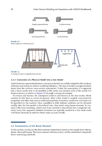
FIGURE 3.9
A swing set and its simplified line model.
3.3.3 Conversion of a Physical Model into a Line Model
Aside from the support idealization, conceptual models are widely adopted in the analyses
of beams and frames to achieve modeling efficiency. The idea of model conceptualization
stems from the uniform cross-section assumption. Under the assumption, it is apparent
that a beam needs only to be modeled at the center axis (neutral axis) of the actual 3-D
beam structure, as shown in Figure 3.9 through a swing set example.
For beams and frames, the conceptual model is also known as the line model, which
consists of only lines or curves in general. After a line model is created, cross-sectional
properties and other data such as material properties, boundary conditions, and loads can
be specified for the analysis. Once a problem is fully defined, solutions can be obtained
readily after the line model is discretized into a line mesh using beam elements. In con-
trast to the truss modeling, where each truss member is discretized into a single bar ele-
ment, many line segments (element divisions) are typically needed in a line mesh made
with beam elements in order to obtain more accurate results.
3.4 Formulation of the Beam Element
In this section, we discuss the finite element formulation based on the simple beam theory
(Euler–Bernoulli beam). The beam element stiffness matrix will be established using both
direct and energy methods.