
Page 90 - Finite Element Modeling and Simulations with ANSYS Workbench
P. 90
Beams and Frames 75
q
x
i L j
qL/2 qL/2
2
2
qL /12 i j qL /12
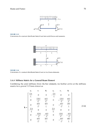
FIGURE 3.13
Conversion of a constant distributed lateral load into nodal forces and moments.
q
L L
qL qL/2
2
qL /12
L L
FIGURE 3.14
Conversion of a constant distributed lateral load on two beam elements.
3.4.4 Stiffness Matrix for a General Beam Element
Combining the axial stiffness (from the bar element), we further arrive at the stiffness
matrix for a general 2-D beam element as
i θ j θ
u i v i u j v j
EA EA
L 0 0 − L 0 0
0 12 EI 6 EI 0 − 12 EI 6 EI
L 3 L 2 L 3 L 2
6 EI 4 EI I 6 EI 2 EI
0 2 0 − 2 (3.12)
k = L L L L
EA EA
− L 0 0 L 0 0
0 − 12 EI − 6 EI 0 12 EI − 6 EI
L 3 L 2 L 3 L 2
0 6 EI 2 2EI 0 − 6EI 4EI
L 2 L L 2 L 