
Page 94 - Finite Element Modeling and Simulations with ANSYS Workbench
P. 94
Beams and Frames 79
From the FE equation, we can calculate the reaction force and moment as
F Y1 EI − 12 6 L pL 2 /
v 2
= 3 − 6 2 2 = 5 2 /
2 θ
M 1 L L L pL 12
where the result in (A) has been used. This force vector gives the total effective nodal
forces, which include the equivalent nodal forces for the distributed lateral load p
given by
−pL/2
2
−pL /12
The correct reaction forces can be obtained as follows:
/
/
F Y1 pL 2 − pL 2 pL
= 5 2 / − − 2 / = 2 2
M 1 pL 12 pL 12 pL /2
Check the results: Draw the FBD for the FE model (with the equivalent nodal force
vector) and check the equilibrium condition.
pL/2 pL/2
2
2
5pL /12 pL /12
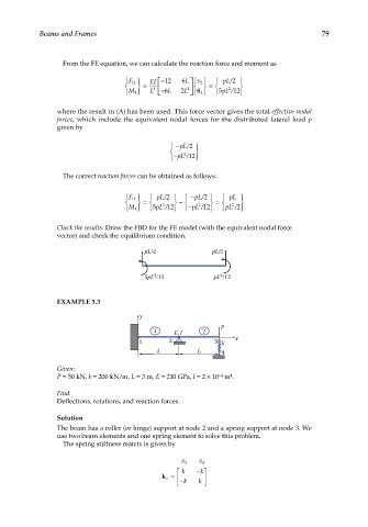
EXAMPLE 3.3
y
P
1 E, I 2
1 2 3 k x
L L 4
Given:
P = 50 kN, k = 200 kN/m, L = 3 m, E = 210 GPa, I = 2 × 10 m .
−4
4
Find:
Deflections, rotations, and reaction forces.
Solution
The beam has a roller (or hinge) support at node 2 and a spring support at node 3. We
use two beam elements and one spring element to solve this problem.
The spring stiffness matrix is given by
v 3 v 4
k − k
s k = −
k k 