
Page 96 - Finite Element Modeling and Simulations with ANSYS Workbench
P. 96
Beams and Frames 81
From the global FE equation, we obtain the nodal reaction forces as,
.
F Y1 − 69 78 kN
.
⋅
M 1 − 69 78 kN m
=
.
F Y 116 2 kN
2
3 488 kN
.
4
F Y
Checking the results: Draw free-body diagram of the beam
69.78 kN 50 kN
1 2 3
69.78 kN · m 116.2 kN 3.488 kN
Sum the forces and moments to verify that equilibrium of the beam is satisfied.
We use the following example to show how to model frames using the general beam
elements. This example can be used to verify the FEA results when using a software
package.
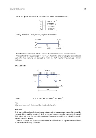
EXAMPLE 3.4
Y 500 lb/ft
3000 lb 1 1 2
E, I, A 2 3 8 ft
3 4 X
12 ft
Given: E = 30 × 10 psi, I = 65 in. , A = 68 in. 2
6
.
4
Find:
Displacements and rotations of the two joints 1 and 2.
Solution
This is a problem of analyzing a frame. Members in a frame are considered to be rigidly
connected (e.g., welded together). Both forces and moments can be transmitted through
their joints. We need the general beam element (combinations of bar and simple beam ele-
ments) to model frames.
For this example, we first convert the distributed load into its equivalent nodal loads
to obtain the following FE mode.